


Introduction
In various industrial setups for cooling and heating, designers often run into a quite annoying block. During the early planning stage, they size the gear based on label details or basic math, making sure there is plenty of heat transfer space. However, after the system starts up and goes into use, a strange problem shows up: even if the flow amounts and starting temperatures on the warm and cool sides match the plan exactly, the end fluid keeps missing the needed “target temperature.” This happens a lot, and it points to deeper issues in how the system really works, not just the size of the parts.
This heat gap is more than a small bother. A difference of only a couple degrees can make the heat work of the whole line drop fast, which raises power use, hurts output quality, and cuts down on total amount handled. As a top maker of smart heat control tools, Grano has seen and fixed this same case for many factory customers. In this full guide, we look at the hidden fluid and heat reasons for this event and show why just putting in more surface space is seldom the right fix. We also share tips from real jobs to help you spot and solve these problems without wasting time or money.
1. The Common Phenomenon of Substandard Target Temperatures
When planning a heat system—for things like controlling temperature in chemical reactors, cooling in building air systems, or heating milk in food plants—designers figure the needed heat load and choose a plate heat exchanger (PHE) to fit. The usual thought is that if the real heat exchange space is big enough, the fluid will easily get to the wanted end temperature.
But in real running, things often do not go as hoped. Workers might see that the cooling water comes in good supply and the warm fluid flow stays steady, yet the work fluid leaves at a temperature that stays 2°C to 5°C below the goal. This problem shows up most in jobs with long heat steps or tight temperature changes (where the cool end temperature needs to go above the warm end temperature). These cases need careful setup to work right, and small mistakes can cause big drops in results.
2. Common Misconceptions in Selection and Troubleshooting
When a system does not hit its target temperature, people often fall into two usual wrong ideas for fixing it:
“The heat exchange area is insufficient.” This makes plant heads add more plates to the stack without thinking. They figure that making the heat exchanger bigger will just pick up the lost degrees.
“The pump flow rate is too low.” This makes them change to bigger, stronger pumps to push more fluid through the setup.
These quick fixes miss the main point of plate heat exchanger design: the precise matching of the plate corrugation angle and the internal channel configurations. The full surface space is just the starting base for heat control. The real way to fix the heat block is in how well that space gets used by the fluid movement inside the unit. Ignoring this leads to wasted effort and ongoing problems, so a full check is key before changes.
3. The Role of Corrugation Angles in Heat Transfer and Resistance
The main tech in a plate heat exchanger is not only the slim metal plates, but the well-made “chevron” (or herringbone) wavy patterns pressed into them. These patterns control how the fluid moves, setting the mix between heat pass rate and pressure loss.
Wavy patterns usually split into two basic types:
High-Theta Plates (Hard Plates / H-Plates): These plates have wide chevron angles. When put together, they make the fluid turn direction fast and often. This builds strong swirling, giving top heat pass numbers (U-values). But this strong swirl costs a lot of fluid push-back, leading to high pressure loss.
Low-Theta Plates (Soft Plates / L-Plates): These have sharp chevron angles. The fluid meets little push-back, letting it flow easy with very low pressure loss. The downside is weaker swirl, so the heat pass number is lower too.
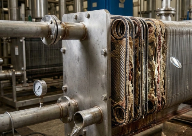
If a heat exchanger uses only easy-flow L-plates to cut pump power, the fluid will go through the paths too smooth. The swirl strength will not be enough to clean and break the tiny heat barrier layer that builds on the metal side. When this occurs, a odd situation happens: the area is theoretically large enough, but the fluid flows away before the heat has been fully exchanged. This mismatch shows why picking the right plates matters so much for steady work.
Table: Performance Comparison of Plate Corrugation Angles
|
Feature |
High-Theta Plates (H-Plates) |
Low-Theta Plates (L-Plates) |
Mixed Channels (M-Channels) |
|
Chevron Angle |
Obtuse (Typically >90°) |
Acute (Typically <90°) |
Alternating H and L plates |
|
Turbulence Intensity |
Very High |
Low |
Moderate to High |
|
Heat Transfer Coefficient |
Maximum |
Minimum |
Highly Optimized |
|
Pressure Drop |
High |
Low |
Moderate |
|
Ideal Application Profile |
Close temperature approaches, extreme temperature crosses |
High flow volumes, strict pressure drop limitations |
Complex industrial processes requiring balanced thermal/hydraulic performance |
This table gives a clear side-by-side view of how different plate types perform, helping you pick the best for your needs. It highlights the trade-offs, so you can balance heat work with flow ease in your setup.
4. Mismatch of Thermal Mixing and Logarithmic Mean Temperature Difference
In tough work conditions with long heat paths and small temperature gaps (extreme temperature crosses), fluids need more stay time and strong heat mixing to finish the heat swap job.
In heat science, the heat swap depth needed for the job is measured by the Number of Transfer Units (NTU). If the wrong mix of plate wavies is picked for these hard conditions, the real NTU made by the heat exchanger will not meet the job needs. Even if you make the total heat space twice as big, the bad heat mixing will stop the system from beating the set limits by the Logarithmic Mean Temperature Difference (LMTD). Heat will just not reach the middle of the fluid path. To avoid this, always match the design to your exact process demands from the start.
5. The Boundary Layer Effect Caused by Asymmetric Flow Rates
In a large number of everyday factory jobs, the amount of flow on the warm and cool sides does not line up even. For example, in many steam or chemical cooling paths, the cooling water flow might be two or three times that of the warm work fluid.
If you use a basic plate heat exchanger with even flow paths in a uneven flow case, the side with less flow will have much slower fluid speed. This slow fluid shifts to a smooth flow type, building a very thick “thermal boundary layer” against the plate wall. This still layer of fluid works just like a cover that blocks heat, fighting hard against heat move and wiping out the good from the metal space around it. This effect sneaks up and cuts performance without clear signs, so checking flow balances is a must.
Grano Case Study: Overcoming the Thermal Blanket in Chemical Processing
Background: A well-known fine chemical plant had trouble cooling a special organic solvent from 80°C to a firm goal of 35°C with 25°C chilled water. The cooling water flow was twice the solvent flow (a 2:1 ratio). This setup is common in chemical work, but it needs special handling to work well.
The Problem: The plant first put in a standard even plate heat exchanger. When the solvent temperature stuck at 39°C, the workers thought they needed more space and added 20% more plates. Oddly, the end temperature did not get better. This showed that size alone was not the issue.
The Grano Solution: Grano’s heat designers checked the system and quickly saw the thermal boundary layer problem. More plates had just made the total path wider, slowing the solvent speed more and making the block layer thicker. Grano swapped the unit for an advanced Asymmetric Plate Heat Exchanger. By making the path tighter on the solvent side and keeping it wider on the water side, the solvent speed picked up a lot into a swirling state without holding back the cooling water flow. This change fixed the core issue at its root.
The Result: The block layer broke apart. The system hit the 35°C target easy, and the full heat pass number went up by more than 40%—all with a smaller real size than the old even unit. This win cut costs and boosted output, proving the value of right design.
6. Comprehensive Factors to Consider for Overcoming Temperature Bottlenecks
To fix temperature blocks for good, designers must look beyond just surface space and do checks across the whole system from fluid move and heat views.
When working with Grano to plan or fix your heat move gear, we look closely at these points:
The Actual Flow Rate Ratio: We study the gap between warm and cool side amounts to see if an uneven path design is needed to keep swirling speed on both sides. This step ensures even work without weak spots.
Target Number of Transfer Units (NTU): We check the real heat depth your job needs, making sure the picked plates can give the right heat mixing. Matching this keeps things on track.
Maximum Allowable Pressure Drop: We see pressure loss not as a bad thing, but as a tool. We use the most allowed system pressure loss to make the top swirl strength, raising the heat pass number. This smart use saves power in the long run.
Current Plate Corrugation Combination: We review each path to decide if your system needs a full H-path, a full L-path, or a custom M-path (mixed) setup. This fine-tuning fits your exact needs.
Seeing that real space is only part of the picture is the first move to real heat improvement. By paying attention to flow move, plate shape, and barrier layer control, Grano makes sure your jobs hit target temperatures right, with good use of power, and without fail. Our approach has helped many clients in different fields, and we stand ready to do the same for you with proven methods and support.
FAQ
Q: Why shouldn’t I just add more plates when my heat exchanger isn’t reaching the target temperature?
A: Adding more plates makes the full cross-area of the fluid path bigger. If your temperature problem comes from low fluid speed and a thick thermal boundary layer, adding plates will slow the fluid even more. This cuts swirl, makes the heat pass number worse, and can speed up dirt buildup. It is key to check the wavy angle and flow move before changing the plate stack. Skipping this can lead to more issues down the line.
Q: How do I know if my process requires an asymmetric plate heat exchanger?
A: Uneven heat exchangers work best when there is a big difference in flow amounts between the main and side fluids (often a 2:1 ratio or more). If you use much more cooling water than your work fluid, a basic even heat exchanger will make the low-flow side slow and not good at work. An uneven design makes sure top speed and swirl stay on both sides at once. This keeps everything running smooth and efficient.
Q: Can I mix high-theta and low-theta plates in the same heat exchanger?
A: Yes. Mixing plates is a good design plan used by Grano. By putting a high-theta (H) plate next to a low-theta (L) plate, we make an “M-channel” (Mixed channel). This lets designers fit the heat pass rate and pressure loss just right for your job, giving a custom fix that mixes heat work with pump power saving. It is a flexible way to meet different needs without big changes.


