

Introduction
In industrial applications ranging from HVAC to petrochemical processing, the Plate Heat Exchanger (PHE) is the heart of thermal management. Known for their high efficiency and compact design, PHEs are generally reliable. However, a common frustration for facility managers is the shrinking interval between cleaning cycles.
If you find yourself scheduling maintenance shutdowns more frequently than the manufacturer recommends—or more often than in previous years—it is rarely just a “maintenance issue.” It is often a signal that the system conditions have changed or the original design no longer matches the current operational reality.
At Grano, we specialize in diagnosing these thermal challenges. Drawing from our experience in manufacturing and servicing gasketed, brazed, and welded plate heat exchangers, this article explores why your PHE might be fouling too fast and how engineering optimization can solve it.
The Warning Signs: When to Take Action
Before addressing the why, it is crucial to recognize the what. Frequent cleaning is usually preceded by specific performance indicators. If you observe the following, your PHE is struggling:
-
Sharp Decline in Heat Transfer Efficiency: The outlet temperatures are not meeting targets, forcing upstream equipment to work harder.
-
Escalating Pressure Drop: A higher pressure drop indicates that flow channels are narrowing due to deposits.
-
Increased Energy Consumption: Pumps are drawing more power to overcome the resistance in the exchanger.
-
Unstable Operation: Fluctuations in temperature control that were previously stable.
Why is Cleaning Becoming More Frequent?
Cleaning frequency is not arbitrary; it is dictated by the rate of fouling. When this rate accelerates, one of the following factors is usually to blame:
1. Changes in Water Quality or Media
The most common culprit is a change in the fluid properties. If your cooling water source (e.g., river water, cooling tower water) sees an increase in hardness, suspended solids, or biological growth, the original “fouling factor” used in the design calculation may no longer be sufficient.
Table 1: Typical Fouling Factors for Common Fluids
Understanding the potential fouling risk of your medium is the first step in diagnosis.
| Fluid Type | Typical Fouling Factor (m2K/W) | Risk Level |
|---|---|---|
| Demineralized Water | 0.00009 | Low |
| Treated Boiler Feedwater | 0.00018 | Low-Medium |
| Cooling Tower Water (Treated) | 0.00035 | Medium |
| River Water / Sea Water | 0.00053 – 0.00088 | High |
| Heavy Fuel Oil | 0.00088 – 0.00176 | Very High |
2. Inappropriate Plate Type or Channel Selection
A PHE is not a “one-size-fits-all” solution. The geometry of the plate corrugation plays a massive role in self-cleaning.
-
Flow Velocity: If the flow rate is too low, the fluid lacks the shear stress required to scrub the plate surface clean, allowing sludge to settle.
-
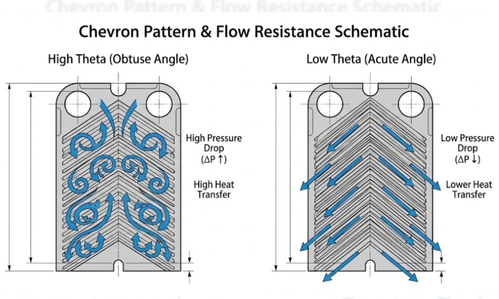
Corrugation Angle: A “soft” plate angle (low theta) offers low pressure drop but generates less turbulence. For dirty fluids, high turbulence (high theta) is essential to keep particles in suspension.
3. Insufficient Pre-Filtration
If the upstream filtration is bypassed or the mesh size is too large for the current debris load, macro-fouling (particulates blocking the inlet ports) will occur rapidly. This is not a heat transfer failure but a system protection failure.
4. The Vicious Cycle of Improper Cleaning
Ironically, cleaning too often or incorrectly can accelerate future fouling.
-
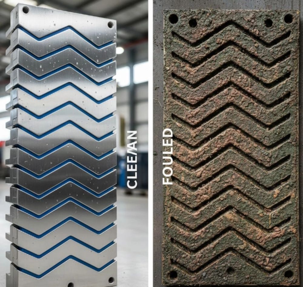
Surface Damage: Aggressive mechanical cleaning (e.g., using steel brushes on stainless steel plates) creates micro-scratches. These scratches act as anchor points for new scale to form more quickly.
-
Chemical Etching: Using the wrong Clean-In-Place (CIP) agents can corrode the plate surface, increasing roughness and promoting bio-film adhesion.
Engineering Optimization: The Grano Solution
Simply cleaning the unit again is a temporary fix. To solve the problem permanently, we recommend an engineering review based on the following three pillars:
1. Re-evaluate Plate Selection
At Grano, we often solve chronic fouling issues by retrofitting the plate pack rather than replacing the entire unit. By switching to plates with a corrugation pattern that induces higher turbulence at your specific flow rate, we can significantly reduce the fouling rate.
Tip: Ensure your flow velocity remains above the critical shear stress threshold (typically $>0.3$ m/s for water) to maintain the self-cleaning effect.
2. Optimize Filtration
Upgrade upstream filtration to capture particulates before they enter the PHE. For open cooling tower systems, side-stream filtration is often a cost-effective upgrade that reduces the sediment load on the heat exchanger.
3. Adjust Cleaning Protocols
Move from reactive cleaning to condition-based maintenance. Use real-time monitoring of pressure drop and temperature differences to determine the optimal time for cleaning. Furthermore, ensure that your cleaning agents are compatible with your plate material (Stainless Steel, Titanium, etc.) and gasket type (EPDM, NBR).
Industry Case Study: Petrochemical Cooling Loop
The Challenge:
A petrochemical facility was using a competitor’s gasketed plate heat exchanger for process water cooling. Due to seasonal algae blooms in the river water feed, the plant was forced to open the unit for manual pressure washing every 3 weeks. This caused significant downtime and accelerated gasket wear.
The Diagnosis:
Grano engineers analyzed the unit and found that the original design prioritized a very low pressure drop, resulting in a low internal flow velocity. The lack of turbulence allowed the biological matter to settle and adhere to the plates rapidly.
The Optimization:
-
Plate Replacement: We replaced the existing plate pack with Grano’s “High-Theta” corrugated plates. This design increased the turbulence and shear stress on the plate wall.
-
Process Adjustment: We slightly increased the pump head to accommodate the marginally higher pressure drop of the new plates.
The Result:
The self-cleaning effect was restored. The maintenance interval extended from 3 weeks to 6 months. The reduction in downtime and gasket replacement costs resulted in an ROI of less than 4 months for the retrofit.
Conclusion
Frequent cleaning is a symptom, not a standard operating procedure. By addressing the root causes—whether it’s hydraulic design, filtration, or water chemistry—you can transform your heat exchanger from a maintenance burden into a reliable asset.
At Grano, we provide high-quality alternatives to major PHE brands, offering drop-in replacement plates and gaskets that are engineered for efficiency and longevity. If your system is demanding too much attention, it’s time to talk to our engineering team.
[Contact Grano Today for a System Evaluation]
FAQ
Q: How do I know if my plate heat exchanger plates are damaged from over-cleaning?
A: Signs of damage include visible scratches or pitting on the metal surface, which often appear duller than the surrounding area. Micro-cracks can also be detected using dye penetrant testing. If plates are scratched, scale will build up significantly faster in those specific areas compared to new plates.
Q: Can I replace my existing plates with Grano plates to improve performance without buying a new frame?
A: Yes, in many cases. Grano manufactures high-quality replacement plates and gaskets that are compatible with frames from major brands like Alfa Laval, GEA, and APV. We can analyze your current frame and propose a plate pack design that is better optimized for your current water quality and flow conditions.
Q: What is the ideal flow velocity to prevent fouling in a PHE?
A: While it varies by fluid viscosity, for water-based applications, a flow velocity between 0.3 m/s and 0.6 m/s is generally considered the minimum to maintain a “self-cleaning” effect through turbulence. Velocities below this range allow suspended solids to settle and fouling to accelerate.
Visit www.grano-heat.com to learn more about our heat transfer solutions.


