


Grano Es un fabricante de intercambiadores de calor fundado en 2015, especializado en intercambiadores de calor de placas, placas para intercambiadores de calor, juntas, unidades, instalación y servicio de mantenimiento. Su línea de productos se utiliza en sistemas de calefacción, climatización, industria química, farmacéutica, alimentaria, energética y de refrigeración industrial.
La base de conocimientos de la empresa también muestra un fuerte enfoque en intercambiadores de calor de placas desmontables, estructura compacta, fácil limpieza, repuestos y servicio en campo. Para los compradores que necesitan tanto suministro de equipos como soporte práctico, el oficial página de servicio y Perfil de la empresa Vale la pena revisarlos antes de que comience un proyecto.
Problema incómodo en el lugar de trabajo: El equipo funciona correctamente, pero la temperatura no alcanza el objetivo.
Algunos problemas en los intercambiadores de calor son ruidosos. Las fugas son evidentes. Las obstrucciones suelen ir acompañadas de una caída de presión. Pero la inversión de la tubería es más preocupante, ya que la unidad puede parecer en perfecto estado desde el exterior. La bomba funciona. Las bridas están secas. El manómetro muestra una lectura normal. Aun así, la temperatura de salida no alcanza el valor previsto.
Sin fugas, presión de la bomba normal, pero rendimiento deficiente en calefacción o refrigeración.
En muchos proyectos reales, la instalación en obra luce impecable. No hay agua en el suelo. La presión de la bomba es estable. El cuadro eléctrico no muestra ninguna alarma. Sin embargo, al comprobar la temperatura de salida, el resultado dista mucho del valor deseado. En un sistema de refrigeración, el agua puede mantenerse más de diez grados por encima de la temperatura requerida. En un sistema de calefacción, la temperatura de salida puede subir demasiado lentamente o detenerse por debajo del punto de ajuste.
En ese momento, a menudo se culpa primero al proveedor del equipo. Una queja común es la siguiente: el intercambiador de calor debe estar defectuoso. El cliente pagó por una determinada capacidad de calentamiento, por lo que un rendimiento deficiente en cuanto a temperatura se percibe como un problema del producto.
Pero si no hay fugas, ni obstrucciones evidentes, ni anomalías de presión, el problema podría no estar en la superficie de la placa, sino en la dirección del flujo.
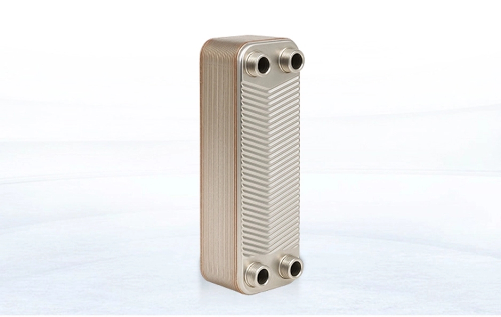
Un intercambiador de calor de placas depende de un flujo de calor óptimo. Según la documentación, está compuesto por placas de transferencia de calor, juntas de sellado, placas de sujeción y pernos de sujeción. Las placas de intercambio de calor presentan cuatro orificios para el flujo, una corrugación en espiga en el centro y ranuras de sellado alrededor de las placas. El fluido de trabajo fluye a través de canales estrechos y sinuosos entre las placas para intercambiar calor. Este diseño genera una fuerte turbulencia y un alto coeficiente de transferencia de calor.
Puede sonar técnico, pero en la práctica es sencillo: el fluido debe entrar y salir por los puertos correctos. Si la entrada y la salida están conectadas en la dirección incorrecta, la unidad aún puede dejar pasar agua, pero el circuito térmico previsto se interrumpe.
| Síntoma en el sitio | Lo que la gente suele sospechar | ¿Qué más se debe revisar? |
|---|---|---|
| No hay fugas de agua | El estado de la junta es bueno. | La dirección de la tubería aún podría ser incorrecta. |
| Presión normal de la bomba | No hay obstrucción grave. | Es posible que el flujo esté pasando por el puerto incorrecto. |
| Temperatura de salida deficiente | La superficie de intercambio de calor es demasiado pequeña. | El diseño a contracorriente puede haberse convertido en diseño en paralelo. |
| El sistema no emite ninguna alarma. | El equipo funciona con normalidad. | El método de ajuste de temperatura podría estar fallando. |
| Gran diferencia con respecto a la temperatura objetivo. | Error de selección de producto | Las conexiones del lado caliente y del lado frío pueden estar invertidas. |
Error fundamental: “Mientras haya una entrada y una salida, las tuberías se pueden conectar de la manera más sencilla”.
Este error suele comenzar con un pequeño atajo. Un soldador o instalador puede elegir la ruta de tubería que evita codos, ahorra material o tiene un aspecto más limpio. En una obra con mucho trabajo, esa elección puede parecer razonable. Pero los intercambiadores de calor no son simples cajas de agua. La disposición de los puertos forma parte del diseño térmico.
Ignorar las marcas de entrada y salida para ahorrar trabajo en las tuberías.
Durante la conexión de las bridas, el instalador puede ignorar las marcas de entrada y salida en la placa de identificación. Los fluidos calientes y fríos pueden conectarse con la entrada superior y la salida inferior. El recorrido de la tubería parece más corto y la instalación también se ve más ordenada. En una sala de máquinas con espacio reducido, esto incluso puede ser bien recibido por ahorrar espacio. Sin embargo, pequeñas ventajas en la longitud de las tuberías pueden generar grandes pérdidas de calor.
La base de conocimientos indica claramente que la instalación de las tuberías de entrada y salida de fluidos fríos y calientes debe seguir las instrucciones especificadas en la placa de características del fabricante. Asimismo, señala que las tuberías conectadas al intercambiador de calor deben limpiarse para evitar que arena, grava, escoria de soldadura y otros residuos entren en la unidad y provoquen obstrucciones.
En un intercambiador de calor de placas estándar, la conexión correcta no es solo una regla de instalación precisa, sino que influye en todo el proceso de intercambio de calor. Las placas se prensan, se disponen y se sujetan según un diseño de combinación de procesos. Durante el montaje, es fundamental mantener la orientación correcta de las placas para evitar la pérdida de eficiencia en el intercambio de calor.
Aquí es donde el error básico se vuelve costoso. La máquina no tiene fugas. La bomba funciona correctamente. El material de las placas puede estar bien. La conexión simplemente fuerza al fluido a circular de una manera para la que el intercambiador no fue diseñado.
Por qué este error de bajo nivel puede parecer un problema del producto.
La queja suele dirigirse al proveedor porque el fallo se manifiesta como un rendimiento deficiente en cuanto a la temperatura. Al cliente puede no importarle si el problema se originó en el equipo de instalación, el trazado de las tuberías o el equipo de puesta en marcha. El cliente solo ve que la temperatura de salida es inadecuada.
Por eso son importantes las etiquetas de los puertos, los diagramas y las comprobaciones de puesta en marcha. Antes de que el sistema funcione bajo carga, el equipo debe verificar una por una la entrada y la salida del lado caliente, así como la entrada y la salida del lado frío. Puede parecer tedioso, pero también evita discusiones innecesarias.
Si el proyecto utiliza un formato compacto Intercambiador de calor de placas soldadasLa comprobación de la conexión es aún más importante, ya que la unidad suele seleccionarse para espacios reducidos y requiere una rápida respuesta térmica. Según los datos del producto, los intercambiadores de calor soldados utilizan esta tecnología para soldar placas metálicas y formar una estructura compacta, con resistencia a la corrosión, a altas presiones y una rápida respuesta a los cambios de temperatura.
Principio técnico: Fallo termodinámico causado por el cambio de flujo a contracorriente a flujo en paralelo.
Un intercambiador de calor no genera calor ni frío por arte de magia. Depende de la diferencia de temperatura. Cuanto mayor y más estable sea la diferencia de temperatura en la superficie de transferencia de calor, mejor será el efecto de transferencia de calor. El flujo a contracorriente ayuda a mantener esa diferencia de temperatura útil en toda la unidad.
Diseño de contracorriente de alta eficiencia
En una configuración típica de intercambiador de calor de placas de alta eficiencia, los fluidos caliente y frío se mueven en direcciones opuestas. Por ejemplo, el fluido caliente puede entrar por la parte superior y salir por la inferior, mientras que el fluido frío entra por la inferior y sale por la superior.
Este patrón de contracorriente mantiene activa la fuerza impulsora de la temperatura a lo largo de todo el canal de la placa. En un extremo, el fluido más caliente se encuentra con el fluido frío ya calentado. En el otro extremo, el fluido caliente enfriado se encuentra con el fluido frío más frío. La diferencia de temperatura no desaparece demasiado pronto, por lo que una mayor superficie de la placa realiza trabajo real.
Según la base de conocimientos, las placas de intercambio de calor se instalan invertidas y la ondulación transversal forma miles de puntos de contacto escalonados. El fluido fluye alrededor de estos puntos, generando una fuerte turbulencia y un alto coeficiente de transferencia de calor. Por ello, la unidad puede ofrecer una alta eficiencia de transferencia de calor y una gran capacidad de carga en un cuerpo compacto.
Un intercambiador de calor de placas también ahorra espacio. La presentación del producto destaca como ventajas clave su tamaño reducido, diseño compacto, alta eficiencia, fácil limpieza y diseño modular flexible. El área de intercambio de calor se puede personalizar hasta 5000 m², con una presión máxima de trabajo de hasta 25 MPa y una temperatura máxima de funcionamiento de hasta 200 °C.
| Tipo de equipo | Área de intercambio de calor | Presión máxima de trabajo | Temperatura máxima de funcionamiento | Uso común |
|---|---|---|---|---|
| Intercambiador de calor de placas | Hasta 5000 m² | 25 MPa | 200°C | Climatización, refrigeración industrial, procesamiento de alimentos, petroquímica |
| Intercambiador de calor soldado | Hasta 2500 m² | 40 MPa | 300°C | Productos químicos, petróleo, gas natural, energía eléctrica |
| Intercambiador de calor de carcasa y tubos | Personalizable | 50 MPa | 400°C | Petroquímica, farmacéutica, siderúrgica, climatización |
| Focas marinas | No aplicable | 50 MPa | -30°C a +250°C | Construcción naval, petróleo, química, energía eléctrica |
Pérdida de transferencia de calor causada por flujo en concordancia
Al invertir la polaridad de las tuberías, el sistema puede pasar de flujo a contracorriente a flujo en paralelo. En el flujo en paralelo, los fluidos calientes y fríos entran por el mismo extremo y se mueven en la misma dirección. La diferencia de temperatura es grande en la entrada, pero disminuye rápidamente a medida que los fluidos avanzan.
Tras recorrer parte del canal, las temperaturas de ambos fluidos se aproximan. La segunda mitad de la zona de transferencia de calor se debilita o prácticamente desaparece. Las placas metálicas siguen ahí. La zona sigue existiendo en teoría. Pero la fuerza impulsora real de la temperatura ha desaparecido.
Por eso, una conexión invertida puede hacer que el equipo parezca insuficientemente dimensionado. En términos técnicos, la mitad del intercambiador realiza el trabajo pesado mientras que el resto simplemente deja pasar el fluido. Algunos ingenieros afirman que este error puede reducir la transferencia de calor efectiva en más del 50 % en casos extremos, especialmente cuando la temperatura de salida requerida es cercana a la temperatura de entrada del fluido opuesto.
Esto no significa que cada tubería invertida cause la misma pérdida. El caudal, el tipo de fluido, la disposición de las placas, el programa de temperatura y la carga de trabajo son factores importantes. Aun así, el error de dirección puede ser lo suficientemente grande como para afectar negativamente la temperatura final de salida.
A Intercambiador de calor de placas soldadas Puede mostrar el problema rápidamente debido a que su paquete de placas compacto responde con rapidez a los cambios de temperatura. En condiciones de funcionamiento que involucren refrigerante, sistemas agua-agua, fluidos químicos o circulación de agua caliente, una dirección incorrecta puede manifestarse como una temperatura inestable, una capacidad deficiente o una desviación constante del punto de ajuste.
| Disposición del flujo | Diferencia de temperatura a lo largo del canal | Resultado de la transferencia de calor | Resultado de campo |
|---|---|---|---|
| Contracorriente | Sigue siendo útil en la mayor parte de la longitud del plato. | Alta eficiencia de transferencia de calor | La temperatura de salida se acerca al valor objetivo de diseño. |
| Cocurrente | Cae rápidamente después de la sección de entrada | Parte del área de la placa pierde efecto real | La temperatura de salida no alcanza el objetivo. |
| Conexión de puerto incorrecta | Rompe con el camino previsto | El rendimiento puede caer drásticamente. | El proveedor podría ser culpado injustamente. |
| Conexión de puerto correcta | Coincide con la placa de identificación y el dibujo. | El área de la placa completa funciona como se esperaba. | Puesta en marcha más sencilla y menos disputas. |
Cómo evitar la inversión de las tuberías antes de la puesta en marcha
La inversión de las tuberías es evitable. Debe detectarse antes del llenado de agua, no después de una acalorada discusión sobre el rendimiento. Una simple revisión puerto por puerto no es sofisticada, pero funciona.
Verifique la placa de identificación, el plano y la dirección del flujo antes de soldar.
Antes de soldar o apretar las bridas, el equipo de instalación debe marcar la entrada y salida de agua caliente, así como la entrada y salida de agua fría, directamente en la tubería. En un entorno polvoriento, una simple marca con bolígrafo no es suficiente. Utilice etiquetas o rótulos temporales que permanezcan visibles hasta que finalice la puesta en marcha.
La orientación de la placa de identificación debe verificarse con respecto al plano del proceso. Si el trazado de la tubería debe modificarse debido a limitaciones del terreno, el equipo de diseño debe confirmar que el nuevo trazado mantiene el patrón de contracorriente requerido. Ahorrar dos codos no justifica la pérdida de toda la capacidad térmica.
Para aplicaciones con mayor presión, fluidos especiales o uso de refrigerantes, se requiere un Intercambiador de calor de placas semi-soldadas Se puede seleccionar el fluido adecuado para que se ajuste mejor al medio y a las condiciones de servicio. Aun así, se mantiene la misma regla: los fluidos caliente y frío deben seguir la dirección de flujo prevista.
Utilice controles de temperatura para detectar el error a tiempo.
Durante la puesta en marcha, se debe medir la temperatura en los cuatro puertos. No se limite a comprobar la salida final. Verifique la entrada y salida de agua caliente, así como la entrada y salida de agua fría. Si observa cambios de temperatura extraños, detenga el proceso y revise las tuberías antes de atribuir la falla a la unidad.
Una configuración normal de contracorriente debería mostrar una distribución de temperatura más lógica en toda la unidad. Un error en la configuración de flujo paralelo suele mostrar un cambio rápido de temperatura cerca de la entrada y una transferencia de calor débil posteriormente. La presión de la bomba puede parecer normal, por lo que basarse únicamente en la presión puede inducir a error al equipo.
La base de conocimientos también señala que el mantenimiento de los intercambiadores de calor debe incluir registros detallados, pruebas de presión después de la limpieza y comprobaciones de grietas o perforaciones durante el desmontaje. Estas prácticas son útiles, pero no debería ser necesario desmontar previamente las tuberías invertidas. La primera comprobación debe ser la dirección de los puertos.
La selección del producto sigue siendo importante, pero la instalación determina el resultado final.
Un buen producto no puede solucionar por sí solo una mala conexión. La selección define la capacidad. La instalación determina si esa capacidad se puede utilizar. Esta es una verdad pequeña pero importante en los proyectos de intercambio de calor.
Adaptar la estructura del producto a las condiciones de funcionamiento.
En sistemas generales de climatización (HVAC), baños, calefacción, refrigeración industrial, industria química, alimentaria y farmacéutica, los intercambiadores de calor de placas desmontables son ampliamente utilizados debido a su tamaño compacto, facilidad de desmontaje y limpieza. Según la información disponible, ocupan poco espacio, son fáciles de instalar y desmontar, ofrecen alta eficiencia de transferencia de calor, permiten un montaje flexible, consumen poco metal y presentan mínimas pérdidas de calor.
Para tareas compactas y de alta presión, un Intercambiador de calor de placas soldadas Puede ser adecuado para aplicaciones químicas, petroleras, de gas natural, de energía eléctrica y de alta temperatura. Para medios de trabajo que necesidad mayor aislamiento entre un lado y el otro, Intercambiador de calor de placas semi-soldadas puede tenerse en cuenta durante la selección técnica.
En una compra real, un comprador puede pasar semanas comparando el material de las placas, el material de las juntas, la presión nominal y el plazo de entrega. Luego, la planta pierde rendimiento porque no se revisaron cuidadosamente cuatro puertos. Es un poco vergonzoso, pero sucede. La solución es simple: considerar la dirección del flujo como parte del rendimiento del producto, no como un detalle menor de instalación.
Preguntas frecuentes
P1: ¿Por qué el intercambiador de calor no alcanza la temperatura objetivo incluso sin fugas?
A: Es posible que las tuberías estén conectadas en la dirección incorrecta. Si el flujo a contracorriente se convierte en flujo en paralelo, la diferencia de temperatura disminuye demasiado rápido y parte del área de transferencia de calor deja de realizar trabajo útil.
P2: ¿Una presión normal en la bomba significa que la tubería está instalada correctamente?
R: No. La presión de la bomba puede parecer normal incluso cuando los fluidos calientes y fríos están conectados con un patrón de flujo incorrecto. Para solucionar este problema, es más útil comprobar la temperatura en los cuatro puertos.
P3: ¿Por qué el flujo a contracorriente es mejor que el flujo en paralelo?
A: El flujo a contracorriente mantiene una mayor diferencia de temperatura a lo largo de una mayor parte de la longitud de la placa. El flujo en paralelo pierde esa diferencia de temperatura rápidamente, por lo que la parte final de la superficie de la placa resulta mucho menos útil.
P4: ¿Debe el instalador seguir al pie de la letra las instrucciones de la placa de identificación?
R: Sí. Las tuberías de entrada y salida del fluido caliente y frío deben seguir la dirección indicada en la placa de características y en el plano técnico. Modificar el recorrido por conveniencia puede provocar una pérdida significativa de rendimiento.
P5: ¿Puede una tubería instalada al revés hacer que una unidad correctamente seleccionada parezca de tamaño insuficiente?
R: Sí. Un intercambiador de calor correctamente seleccionado puede parecer demasiado pequeño si la tubería modifica la trayectoria de flujo prevista. Antes de cuestionar el área de intercambio de calor, conviene verificar primero la dirección de los puertos.


