



A hot engine and a cold-water pipe look like a straightforward heat-recovery opportunity. The awkward question comes later: where does the heat go once the tank is hot? On a biogas plant, that question belongs in the first design discussion, before the heat exchanger is ordered.
For biogas CHP jacket water heat recovery, the receiving water has to be cool enough to accept heat. Meanwhile, the engine needs its own coolant conditions maintained. Putting a plate heat exchanger between the circuits separates the fluids, but it doesn’t settle those operating questions. Work them out together.
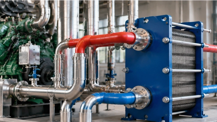
The heat customer must be available when the engine runs
Put the engine operating hours beside the heating schedule. Do they overlap? A digester may need heat while the process-water tank is satisfied; space heating may account for a large winter load and almost nothing in summer. One peak-load number hides all of that. The useful starting point is a schedule showing which load will accept heat, and when.
دی EPA’s description of CHP includes biogas among the fuels for reciprocating engines and describes recovering heat for useful thermal loads. For a project estimate, count the heat the site can consume. Sending hot water around a recovery skid isn’t evidence of a fuel saving if the receiving tank has nowhere else to send it.
There are different numbers behind the word “recovery.” The engine data sheet gives available jacket-water heat. The exchanger calculation gives transferred heat at stated conditions. The site’s operating schedule determines how much of that transfer is useful. Keep these entries separate. Exhaust recovery stays outside the jacket-water calculation unless the engine supplier’s drawing combines the duties.
Include the secondary return temperature in the enquiry, especially its highest expected value. Also write down the zero-demand periods. “Heating water required” is too vague to tell a supplier what happens when that requirement has been met.
Keep jacket water on its own circuit
The engine coolant isn’t ordinary site heating water. The circuits may have different treatment, pressure and maintenance requirements. With an indirect connection, heat crosses a metal wall while the fluids stay on their respective sides. Leakage consequences still need assessment, and both fluids still need condition checks.
The engine sets the return-temperature limit
Use the engine manufacturer’s current specification for coolant flow, temperature range, pressure limits and allowable external pressure drop. A figure from another engine with the same electrical output won’t do. If those documents haven’t arrived, the exchanger enquiry is missing part of its design basis.
Check the proposed return conditions against that specification. A control arrangement that drives the engine return below its permitted temperature needs changing. At the other end of the range, hot secondary return water leaves a smaller temperature difference across the exchanger. Less driving temperature difference means a harder heat-transfer duty.
An exchanger capacity needs four temperatures beside it: inlet and outlet on each side. Without them, two quotations carrying the same kilowatt rating may describe different jobs.
Excess heat still needs a destination
دی EPA reciprocating-engine technology catalogue shows a closed-loop arrangement with a customer heat exchanger and an excess-heat exchanger. The latter rejects heat when the customer cannot use it. This is a general system arrangement, not a specification for a particular Grano installation.
The engine still needs somewhere to reject heat when the site stops taking it. Agree that route with the engine supplier and system designer. Walk through the actual events: the site pump stops; the storage tank reaches temperature; secondary flow is lost. For each event, identify the control response and the equipment that carries the cooling duty. This belongs on the system drawing, not in an assumption attached to the exchanger order.
Specify the plate pack around the operating envelope
For clean liquid circuits, consider a gasketed پلیٹ گرمی ایکسچینجر with access for maintenance. In this construction, bolts hold the clamping plates around a stack of heat-transfer plates. The stack sits on guide rods. Corrugations disturb the flowing liquid, and openings at the plate corners provide the connections through the pack.
Look at the plate drawing during review. The seals also establish the channels between the plates; they aren’t merely an outside boundary around a stack of metal. Assemble the plates in the arrangement on that drawing. Being able to tighten the frame is no assurance that the liquid will take the intended route.
Once opened, the detachable pack exposes the plates for cleaning and examination. Individual damaged plates or seals can be assessed for replacement. That access is useful on a recovery circuit, where a gradual loss of performance needs investigating without guessing at the condition of hidden surfaces. It still doesn’t establish coolant compatibility.
Send the coolant’s formulation and concentration, including its additives. Send the secondary-water information with it. A one-word fluid entry, “glycol,” is easy to put on an enquiry and difficult to design from. Ask for confirmation of the plate and gasket materials against that actual mixture, at its stated temperatures.
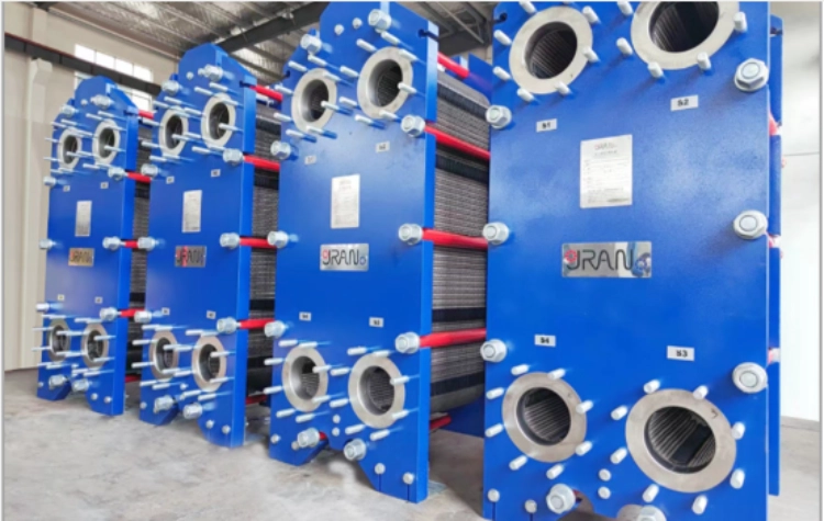
Keep a short set of duty sheets for the review. The normal recovery sheet needs flow and all four temperatures at a representative engine load. A second sheet covers the hottest secondary return. Add the reduced-engine-load condition, using the heat actually available then. Finally, identify the no-demand condition and refer it to the control drawing: the recovery exchanger will not dispose of that excess heat by itself.
There is a hydraulic side to this review as well. How much pump head is left after the rest of the circuit? That remainder has to accommodate the proposed exchanger. Have both side pressure drops written into the selection, so the pumps aren’t left as an assumption for someone else to resolve.
Before accepting the calculation, read its fluid entry. A water calculation needs correcting if the engine uses a glycol mixture. Check where the heat-duty number came from, too. The engine’s total waste heat includes more than the jacket-water contribution.
Plan access before the skid arrives
An exchanger squeezed between the engine and a pipe rack may fit the footprint but leave no room to open the pack. Reserve the space required for maintenance. Check it on the installation drawing, including the route for moving removed plates out to a clean work area. Keep that route clear after commissioning.
Clean assembly and correct connections
Clean the corrugations and gasket grooves before the plates go back into the frame. A seal has to sit in its groove without being twisted or pushed aside. Bring the clamping studs in evenly, working symmetrically so the plates stay parallel. The selected unit’s closing dimension controls the final assembly; extra tightening is not a general cure for leakage.
At the pipe connections, use the inlet and outlet directions on the factory nameplate. Clean the connected pipework before admitting flow. Sand and welding debris have no place in narrow plate passages. It is cheaper to remove them during installation than to stop a newly commissioned plant to find out where they lodged.
Inspection after a performance change
If pressure drop starts creeping up, dirty passages or an obstruction are possibilities. Scale on a plate also resists heat transfer. Compare the reading with the clean starting condition, at comparable flow. Was the secondary return warmer on the day of the complaint? That is worth checking before scheduling an opening.
With the pack open, examine the plates for cracks, holes, pitting or distortion and assess damaged parts for repair or replacement. Look at the seals and clamping, too: aged or off-centre gaskets and uneven bolt tightening can cause leaks. Measure the pack before opening and keep the measurement in the record. On reassembly, return to the approved closing dimension.
These are jobs on the detachable plate exchanger. The engine has its own coolant maintenance procedure. Identify the equipment on each service record so the two don’t get mixed together.
Agree the acceptance measurements
How will the plant demonstrate the purchased duty? Settle that before the order. Specify the test operating condition and the measurements: flow, inlet and outlet temperatures on both sides, and pressure drop. Trying to prove full duty with a lightly loaded engine and an already-hot tank leaves too much room for disagreement.
Use the system designer’s commissioning procedure to check what happens as useful heat demand falls away. The recovery run and the loss-of-load response are different checks. Both matter to the engine installation.
بھیجیں۔ اناج the engine-approved cooling limits, actual coolant composition and secondary-load schedule with the enquiry. Request a selection that states its duty, temperatures, pressure drops, materials and service clearances. That gives the project team a defined interface to review before the exchanger becomes part of the engine installation.


