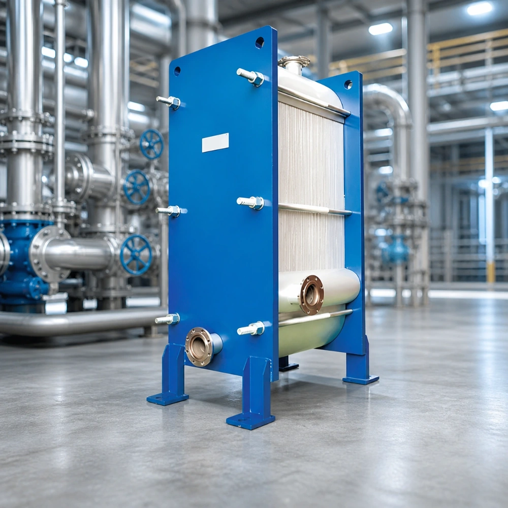

In a кожухотрубный теплообменник, a heat exchanger baffle is not just an internal support plate. Its position, cut, spacing, and clearance influence how shell-side fluid moves across the tubes. That affects heat transfer, pressure drop, tube vibration, cleanability, and the risk of local erosion. A baffle arrangement that works for one service can be a poor choice for another.
This matters when a buyer reviews a new design, investigates an underperforming unit, or replaces damaged internals. The practical question is not whether the exchanger has baffles. It is whether the baffle layout creates the required shell-side flow without imposing an unacceptable pressure or maintenance burden.
What a Baffle Does Inside the Shell
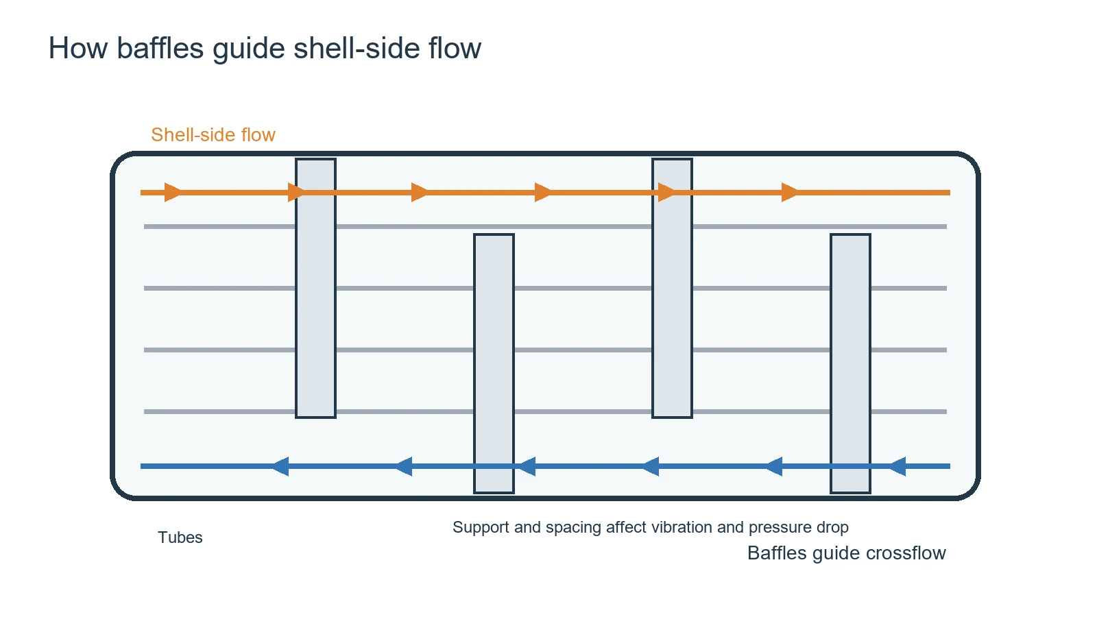
Shell-side fluid would tend to take the easiest path from inlet to outlet if the shell were left open. It could flow mainly along the shell, bypass large parts of the tube bundle, and leave some tubes poorly washed. Baffles interrupt that path and guide the fluid across the tube bundle. The resulting crossflow can improve mixing and the temperature driving force around the tubes.
Baffles also support the tubes between the tube sheets. That support reduces the free span over which tubes can vibrate under flow-induced forces. The baffle therefore has two jobs that must be considered together: it shapes the shell-side flow and it restrains the mechanical movement of the tube bundle.
How Baffles Change Heat Transfer
More effective crossflow usually improves the shell-side film coefficient compared with a long, weakly guided flow path. But the gain is not free. More changes in direction and higher local velocity increase frictional resistance. A design that pushes heat transfer too aggressively can exceed the available pump or compressor head and reduce the useful operating range.
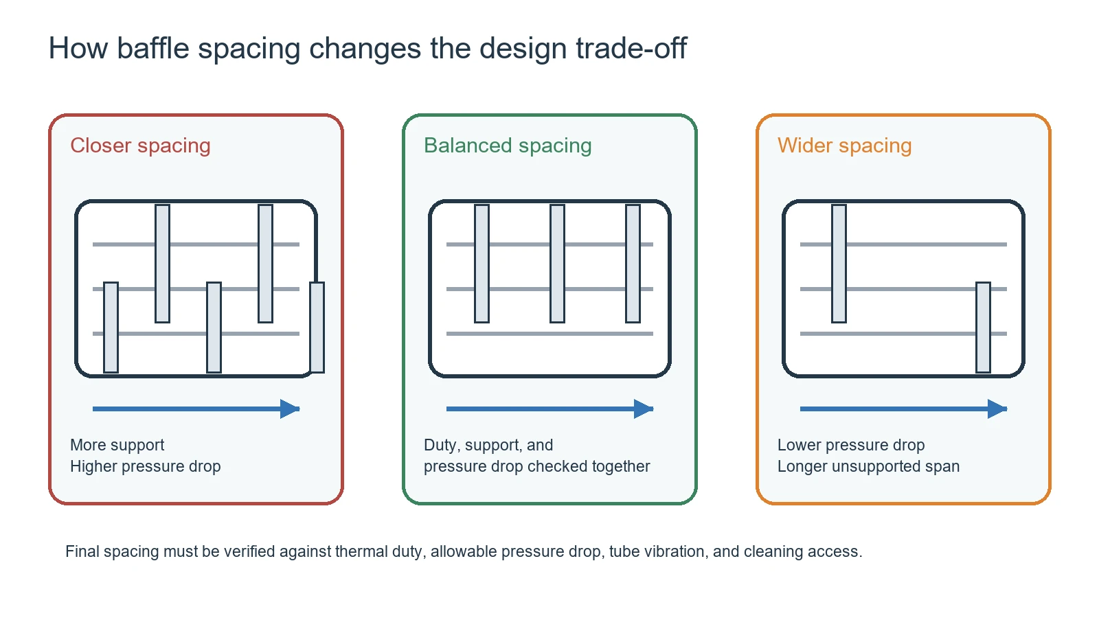
Baffle cut and spacing work together. A smaller cut can force more fluid across the tubes, while a larger cut gives the fluid a more open passage. Closer spacing provides more tube support and more frequent redirection, but it can also raise pressure drop and make mechanical cleaning harder. There is no universal best percentage or spacing without the shell diameter, tube layout, fluid properties, thermal duty, and allowable pressure drop.
The Main Baffle Variables Buyers Should Review
|
Variable |
What it changes |
What to ask for |
|
Baffle type |
Flow path, support pattern, and service access |
Why this type fits the process and cleaning method |
|
Baffle cut |
Open flow area and crossflow intensity |
Design basis and shell-side pressure-drop result |
|
Baffle spacing |
Tube support, velocity profile, and pressure drop |
Minimum and maximum spacing used in the design |
|
Clearance |
Bypass flow and local wear |
Shell, tube, and baffle tolerances |
|
Support details |
Vibration and bundle stability |
Tie rods, spacers, pass lanes, and tube support |
A quotation that only states the shell diameter and tube count does not tell a buyer enough about the baffle design. The thermal calculation, pressure-drop calculation, general arrangement drawing, and materials list should be reviewed together.
Why Bypass Flow and Leakage Paths Matter
Not all shell-side fluid follows the intended crossflow path. Clearance between the baffle edge and shell, gaps around the tube bundle, and openings near pass lanes can create bypass or leakage streams. These streams may carry fluid through the shell without contacting the tubes as intended. The unit can then show a lower-than-expected duty even when the total flow rate looks correct.
A designer may use sealing strips or other details to control a bypass path, but the right solution depends on the construction and service. Excessive restriction can raise pressure drop, while excessive clearance can reduce the effective flow through the bundle. If performance is below the design value, the investigation should compare the as-built clearances and baffle arrangement with the approved drawing.
Baffles, Vibration, and Tube Damage
Flow-induced vibration is a mechanical risk, not only a noise problem. Repeated tube movement against a baffle hole can produce fretting, wear, and eventually a leak. Large unsupported spans, an unsuitable flow velocity, loose supports, or a damaged baffle can increase the risk. A high pressure drop does not prove that the tube bundle is mechanically safe, and a quiet exchanger does not prove that there is no fretting.
During inspection, look for polished wear marks, local thinning near support points, enlarged baffle holes, bent support plates, loose tie rods, damaged spacers, and deposits that change the intended flow path. The inspection should consider both the tube surface and the baffle support condition.
How to Select Baffles for the Service
Clean liquids
For relatively clean liquids, the design can focus on the required duty, allowable pressure drop, tube support, and controllable velocity. The buyer should still confirm how the unit will be drained, vented, opened, and inspected.
Fouling or solids-bearing fluids
When the shell-side fluid carries solids or forms deposits, a tight baffle layout may complicate cleaning and create local accumulation. The design review should ask about removable bundle access, mechanical cleaning routes, flushing, drain points, and the expected fouling pattern. A higher calculated heat-transfer coefficient is not useful if the exchanger cannot be maintained.
Viscous or temperature-sensitive fluids
Viscosity changes the velocity profile and pressure-drop balance. Temperature-sensitive products may also need a controlled flow path that avoids local overheating or excessive residence time. The fluid properties used in the calculation should match the actual operating temperature range rather than a single convenient value.
Condensing or boiling shell-side service
Phase-change service can require a different approach to drainage, vapor distribution, liquid level, and support. Baffles should not be selected only by copying a single-phase liquid arrangement. The thermal designer should explain how the baffles support distribution and avoid trapping liquid or gas in the intended operating orientation.
Diagnosing Poor Performance in an Existing Unit
If a shell-and-tube exchanger does not meet its duty, do not change baffles before confirming the measurement. Check inlet and outlet temperatures, flow rates, fluid properties, fouling, instrument accuracy, and pressure drop on both sides. A fouled tube bundle or incorrect flow estimate can look like a baffle problem.
- Compare actual shell-side pressure drop with the original design value.
- Check whether the actual flow direction, pass arrangement, and operating temperature match the design.
- Inspect for bypass gaps, damaged seals, missing sealing strips, or a shifted bundle.
- Look for tube fretting, vibration marks, loose supports, and deposits near baffle windows.
- Review whether the fluid has become more viscous, more contaminated, or more corrosive.
What to Request in a New Heat Exchanger Quotation
For a purchase or replacement project, ask the manufacturer to state the baffle assumptions rather than accepting a generic shell-and-tube description. A useful quotation package can include:
- Shell-side flow rate, inlet and outlet temperatures, fluid properties, and allowable pressure drop.
- Baffle type, cut, spacing, orientation, support details, and material.
- Tube layout, tube support arrangement, pass lanes, and cleaning access.
- Thermal duty, design pressure and temperature, test scope, and inspection records.
- General arrangement drawings showing nozzles, bundle access, drains, vents, and clearances.
Грано heat exchanger product information can be used as a starting point when comparing equipment types and project requirements. Its сервисная поддержка is relevant when an existing exchanger needs inspection, cleaning, repair guidance, or a replacement discussion. For a shell-and-tube project, the final baffle arrangement still needs to be confirmed from the specific thermal and mechanical design.
A Practical Baffle Review Checklist
- The shell-side fluid and its property range are defined at the design temperatures.
- The target duty and allowable pressure drop are stated separately.
- Baffle cut, spacing, clearance, and support details appear on the drawing or calculation.
- The design addresses tube vibration, fretting, bypass flow, and erosion.
- Cleaning, draining, venting, and bundle removal are possible for the intended service.
- The quotation identifies the materials, test scope, and documents supplied with the unit.
Часто задаваемые вопросы
Q1: Does a smaller baffle spacing always improve heat transfer?
No. It can increase crossflow and tube support, but it can also increase pressure drop, complicate cleaning, and change vibration behavior. The correct spacing depends on the complete design.
Q2: What happens if the baffle cut is too large?
The shell-side flow may take a less effective path around the baffle window, reducing crossflow across the tubes. The actual effect depends on flow rate, fluid properties, tube layout, and the rest of the baffle arrangement.
Q3: Can baffles cause tube leaks?
They can contribute to tube wear when support holes, clearances, flow velocity, or vibration conditions are unsuitable. Inspection should look for fretting and local wear near the baffle supports.
Q4: Should I specify baffle spacing as a fixed percentage?
A fixed value is not a universal design rule. Ask the manufacturer to justify the spacing using the shell diameter, tube support requirement, pressure drop, fluid properties, and vibration assessment.
Q5: Can I change baffles in an existing exchanger to increase capacity?
Possibly, but it is a redesign rather than a simple modification. The thermal calculation, pressure drop, tube support, clearances, materials, and mechanical integrity must be checked before changes are made.
Заключение
A heat exchanger baffle determines much of the shell-side flow pattern in a shell-and-tube heat exchanger. Baffles can improve crossflow and support the tubes, but they also influence pressure drop, bypass flow, cleaning access, vibration, and local wear. When buying or troubleshooting a unit, ask for the baffle design basis and review it with the thermal and mechanical conditions. The best arrangement is the one that meets the duty while remaining inspectable, maintainable, and mechanically reliable.